- 您现在的位置:买卖IC网 > Sheet目录991 > MXHV9910DB3 (IXYS Integrated Circuits Division)BOARD EVAL FOR MXHV9910
�� �
�
�I� NTEGRATED� C� IRCUITS� D� IVISION�
�It� is� a� good� practice� to� select� a� power� rating� that� is� at�
�least� twice� the� calculated� value.� This� will� give� proper�
�margins,� and� make� the� design� more� reliable.�
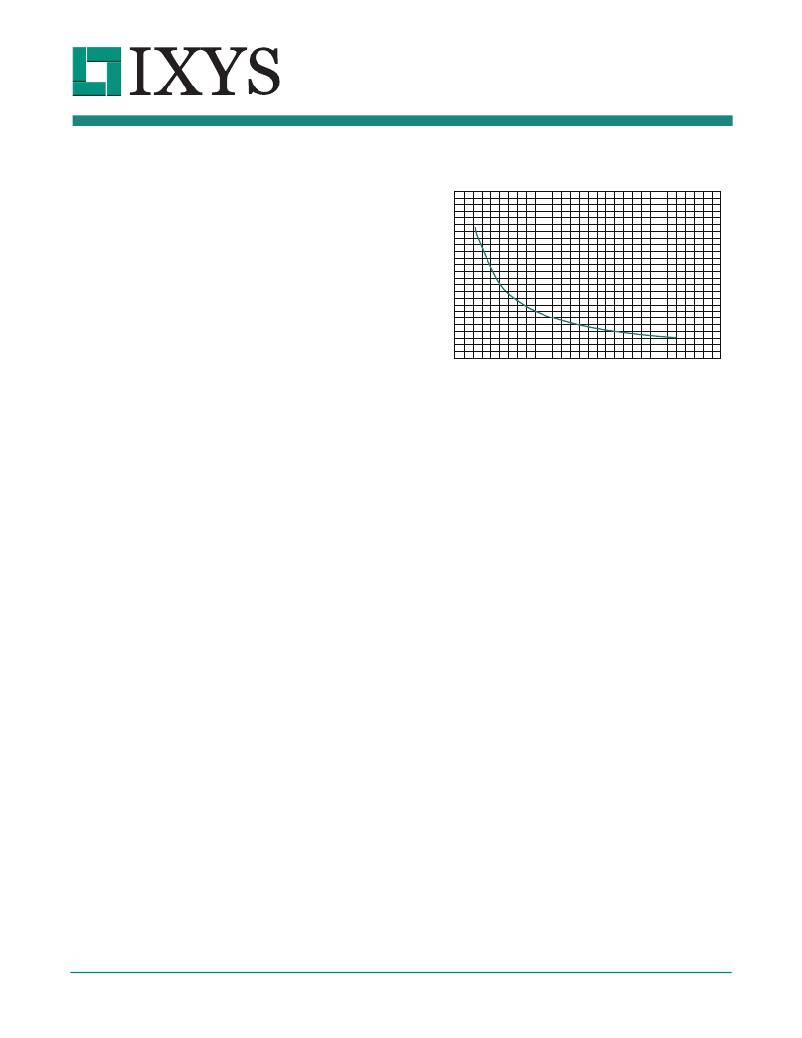
�Figure� 4� Resistor� Selection�
�Oscillator� Frequency,� f� S� ,� vs.� R� T�
�(T� A� =27oC)�
�MXHV9910�
�250�
�2.2.3� Current� Sense� Blanking�
�The� MXHV9910� has� an� internal� current-sense�
�blanking� circuit.� When� the� power� MOSFET� is� turned�
�on,� the� external� inductor� can� cause� an� undesired�
�spike� at� the� current� sense� pin,� CS,� initiating� a�
�premature� termination� of� the� gate� pulse.� To� avoid� this�
�condition,� a� typical� 400ns� internal� leading� edge�
�blanking� time� is� implemented.� This� internal� feature�
�eliminates� the� need� for� external� RC� filtering,� thus�
�200�
�150�
�100�
�50�
�simplifying� the� design.� During� the� current� sense�
�blanking� time,� the� current� limit� comparator� is� disabled,�
�preventing� the� gate-drive� circuit� from� terminating� the�
�0�
�0�
�200�
�400�
�600�
�R� T� (k� Ω� )�
�8� 00�
�1000�
�1200�
�D� max� =� --------------------------�
�t� ONmax� =� -------------�
�?� V� in� –� V� LEDstring� ?� ?� t� ONmax�
�r� iout� ?� I� LED�
�gate-drive� signal.�
�2.2.4� Enable/Disable�
�Connecting� the� PWMD� pin� to� V� DD� enables� the� gate�
�driver.� Connecting� PWMD� to� G� N� D� disables� the� gate�
�driver� and� sets� the� device� into� the� shut-down� mode.� In�
�the� shut-down� mode,� the� gate� output� drive� is� disabled�
�while� all� other� functions� remain� active.� The� maximum�
�quiescent� current� in� the� shut-down� mode� is� 0.6mA.�
�2.2.5� Oscillator�
�The� MXHV9910� operates� in� a� constant� frequency�
�mode.� Setting� the� oscillator� frequency� is� achieved� by�
�connecting� an� external� resistor� between� R� T� and� G� N� D.�
�In� general,� switching� frequency� selection� is� based� on�
�the� inductor� size,� controller� power� dissipation,� and� the�
�input� filter� capacitor.�
�The� typical� off-line� LED� driver� switching� frequency,� f� S� ,�
�is� between� 30kHz� and� 120kHz.� This� operating� range�
�gives� designers� a� reasonable� compromise� between�
�switching� losses� and� inductor� size.� The� internal� RC�
��shows� the� R� T� resistor� selection� for� the� desired� f� S� .�
�2.2.6� Inductor� Design�
�The� inductor� value� is� determined� based� on� LED� ripple�
�current,� maximum� on-time,� the� forward� voltage� drop� of�
�all� LEDs� in� a� string� at� the� desired� current,� and� the�
�minimum� input� voltage,� which� is� based� on� design�
�requirements.� The� maximum� on-time� is� determined� by�
�the� duty� cycle� and� switching� frequency.� The� maximum�
�duty� cycle� is� given� by:�
�V� LEDstring�
�V� in�
�Where:�
�?� V� LEDstring� is� the� LED� string� voltage� at� desired�
�average� LED� current.�
�?� V� in� is� the� minimum� input� voltage� to� V� I� N�
�The� maximum� duty� cycle� must� be� restricted� to� less�
�than� 50%� in� order� to� prevent� sub-harmonic� oscillations�
�and� open� loop� instability.�
�The� converter� maximum� O� N� -time� is� given� by:�
�D� max�
�f� s�
�Where� f� s� is� the� switching� frequency� of� the� internal�
�oscillator.�
�The� inductor� value� for� the� given� ripple� is:�
�L� min� =� ---------------------------------------------------------------------�
�R03�
�www.ixysic.com�
�7�
�发布紧急采购,3分钟左右您将得到回复。
相关PDF资料
MXJA01JA2000
COAX CONN WITH CABLE 200MM
MY4H-US AC110/120
RELAY GEN PURPOSE 4PDT 3A 120V
N001-003-BK-R
CABLE PATCH CAT5E BLACK 3'
N001-003-BK
CABLE PATCH CAT5E BLACK 3'
N001-003-BL-R
CABLE PATCH CAT5E BLUE 3'
N001-003-BL
CABLE PATCH CAT5E BLUE 3'
N001-003-GY-R
CABLE PATCH CAT5E GRAY 3'
N001-003-GY
CABLE PATCH CAT5E GRAY 3'
相关代理商/技术参数
MXJ-0902-17
制造商:PDI 制造商全称:PDI 功能描述:SURFACE MOUNT MIXER
MXJ-2001-10
制造商:PDI 制造商全称:PDI 功能描述:SURFACE MOUNT MIXER
MXJ-2001-13
制造商:PDI 制造商全称:PDI 功能描述:SURFACE MOUNT MIXER
MXJ-2001-17
制造商:PDI 制造商全称:PDI 功能描述:SURFACE MOUNT MIXER
MXJ-2001-7
制造商:PDI 制造商全称:PDI 功能描述:SURFACE MOUNT MIXER
MXJ-2201-10
制造商:PDI 制造商全称:PDI 功能描述:SURFACE MOUNT MIXER
MXJ-2201-13
制造商:PDI 制造商全称:PDI 功能描述:SURFACE MOUNT MIXER
MXJ-2201-17
制造商:PDI 制造商全称:PDI 功能描述:SURFACE MOUNT MIXER